


The versatility of PCIe slots in 2U chassis is a cornerstone of modern server design, enabling the integration of high-performance full-height, full-length cards like FPGAs and NICs through strategic riser configurations that maximize density without sacrificing critical expansion capabilities.
How does a2U server chassis physically accommodate full-height, full-length PCIe cards?
2U chassis, standing3.5 inches tall, cleverly reorients expansion cards horizontally using riser boards. This turns the vertical space limitation into a lateral advantage, allowing cards to lie flat. Server designers allocate continuous real estate along the chassis length, ensuring no internal components obstruct the typical12.3-inch card length.
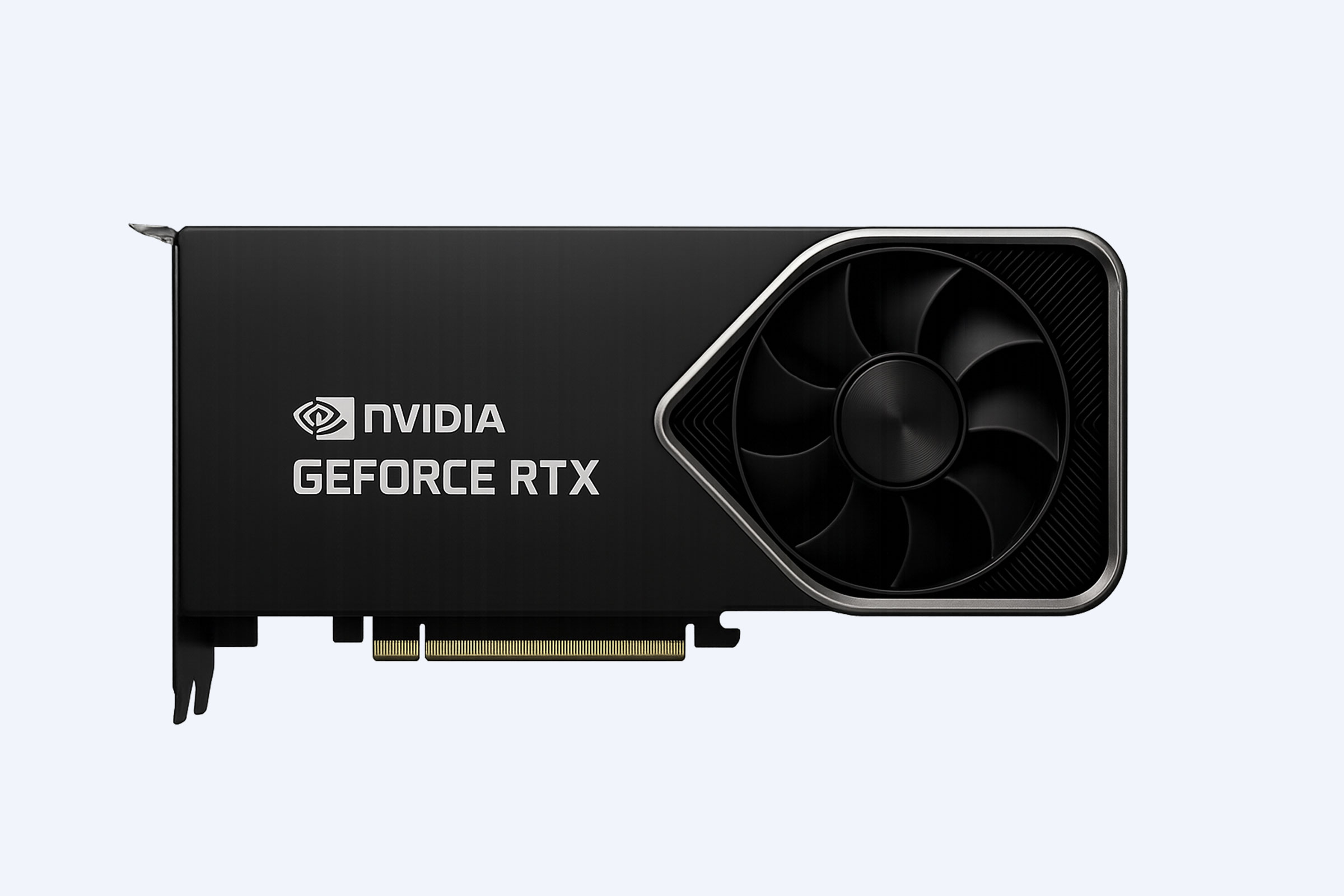
The physical accommodation is an engineering feat of spatial optimization. A standard2U server internally dedicates a specific zone, often behind the drive bays, for a horizontal card cage. A riser card plugs perpendicularly into the motherboard’s PCIe slot and provides one or more horizontal slots. This configuration effectively uses the chassis’s depth, which is substantial, often exceeding30 inches. For instance, installing a high-end NVIDIA A10080GB GPU, a full-height, full-length card, requires precise planning for airflow and power delivery alongside the riser mechanism. The key is ensuring the riser assembly and the card’s bracket are properly anchored to the chassis to prevent flex during shipping. How do you think a riser card manages signal integrity over this new physical path? And what happens to thermal dynamics when a card is mounted parallel to the motherboard? Transitioning to this layout, it’s crucial to verify the chassis’s specified maximum card dimensions, as even a millimeter of overhang can interfere with cable management or cooling fans. Ultimately, this horizontal mounting is analogous to books lying flat on a shelf rather than standing upright; it uses the available shelf length efficiently, though it requires a supportive structure—the riser—to access them.
What are the common riser configurations and slot layouts found in2U servers?
Riser configurations in2U servers are designed to maximize slot count and bandwidth within the constrained height. Common layouts include single, dual, and even triple riser designs, each offering different combinations of x16, x8, and x4 mechanical slots, often bifurcated from the CPU’s PCIe lanes to serve multiple cards.
Server manufacturers employ several standard riser topologies to balance density with flexibility. A ubiquitous configuration is the2U3-slot riser, which might present three full-height, full-length x16 slots, though their electrical wiring varies. Another popular layout is a dual-riser system where one riser holds two x16 slots and another holds one, allowing strategic placement of the most bandwidth-hungry cards. The slots themselves can be physically x16 but electrically wired as x8 or x4, depending on the motherboard’s PCIe lane distribution and the need for more slots. For example, a system might use PCIe bifurcation to split a CPU’s x16 link into two x8 connections on the riser, enabling two high-performance network cards to run simultaneously. Isn’t it fascinating how a single physical connector can be logically divided? However, this lane sharing necessitates understanding the total bandwidth pool. Moving from theory to practice, the choice of configuration directly impacts what you can deploy; a triple-x16 riser is ideal for GPU or FPGA clusters, while a mix of x8 and x4 slots suits a blend of NICs and storage controllers. Therefore, scrutinizing the riser’s block diagram is as important as counting the slots.
| Common Riser Configuration | Typical Slot Layout (Mechanical/Electrical) | Ideal Use Case Scenario | Key Consideration |
|---|---|---|---|
| Single Riser,3-Slot | 3 x x16 slots (x16/x8/x8 or x8/x8/x8) | Dense GPU acceleration for AI training or high-frequency trading FPGAs | Requires high-wattage power supply and robust cooling for multiple300W+ cards |
| Dual Riser,3-Slot Total | Riser A:2 x x16 (x16/x8), Riser B:1 x x16 (x8) | Mixed workload with two GPUs and one high-speed NIC (e.g.,200GbE) | Check motherboard lane allocation to avoid bandwidth contention between risers |
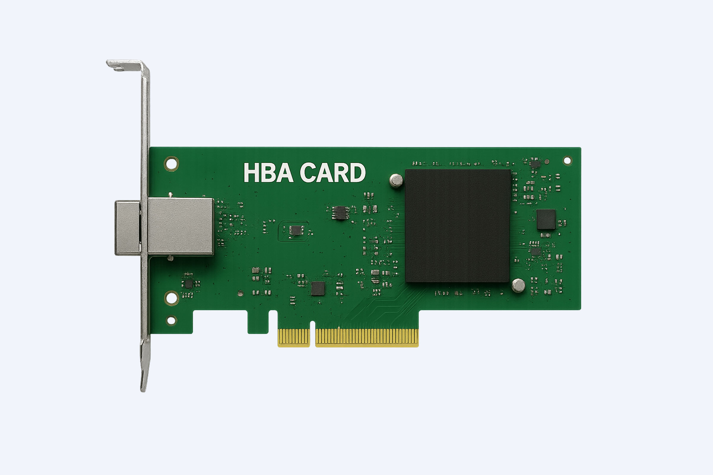
| Dual Riser,4-Slot Total | Riser A:2 x x16 (x8/x8), Riser B:2 x x8 (x4/x4) | Storage-heavy server with NVMe adapters and SAS HBAs alongside a single GPU | Lower-profile cards may be needed on the x8 slots due to adjacent component clearance |
| Triple Riser,6-Slot Total | 3 risers each with2 x x8 slots (electrically x4) | Network appliance or security gateway with many25GbE or100GbE NICs | Extensive PCIe switching is likely involved, adding minor latency; focus on airflow across many cards |
Why is PCIe slot placement and airflow so critical for high-power cards in2U?
Placement and airflow are critical because high-power cards like GPUs and FPGAs generate immense heat in a confined2U space. Poor layout leads to thermal throttling, reduced card lifespan, and system instability. Strategic slot spacing and directed airflow are non-negotiable for reliable operation.
The thermal challenge in a2U chassis is profound. A card like an NVIDIA H100 PCIe can dissipate over350 watts, essentially acting as a small space heater. If two such cards are placed adjacent in a riser with no gap slot between them, they will starve each other of cool air, causing intake temperatures to soar. Server designs mitigate this with blower-style coolers on the cards that exhaust hot air directly out the rear I/O shield, but this only works if the chassis airflow is organized to feed them. Proper placement often means leaving an empty slot between high-power cards to create an air channel, or using slots that align with the chassis’s high-pressure fan wall. Imagine a narrow hallway with multiple ovens turned on; without a strong, directed wind to carry the heat away, the environment becomes unbearable. Does the server’s fan control policy ramp up adequately based on PCIe card temperature sensors? Furthermore, the riser’s placement relative to the power supply unit and CPU heatsinks can create hot air recirculation zones. Consequently, when planning a deployment, you must consult the server’s thermal design guide, which specifies acceptable card power limits per slot. Ignoring these guidelines is a direct path to performance degradation and hardware failure.
What are the key differences between using PCIe slots for NICs versus FPGAs or GPUs?
The key differences revolve around bandwidth consistency, latency sensitivity, power and thermal footprint, and driver/software stack. NICs prioritize consistent, low-latency packet flow, while GPUs/FPGAs demand massive, burstable bandwidth for parallel computation and have significantly higher power and cooling requirements.
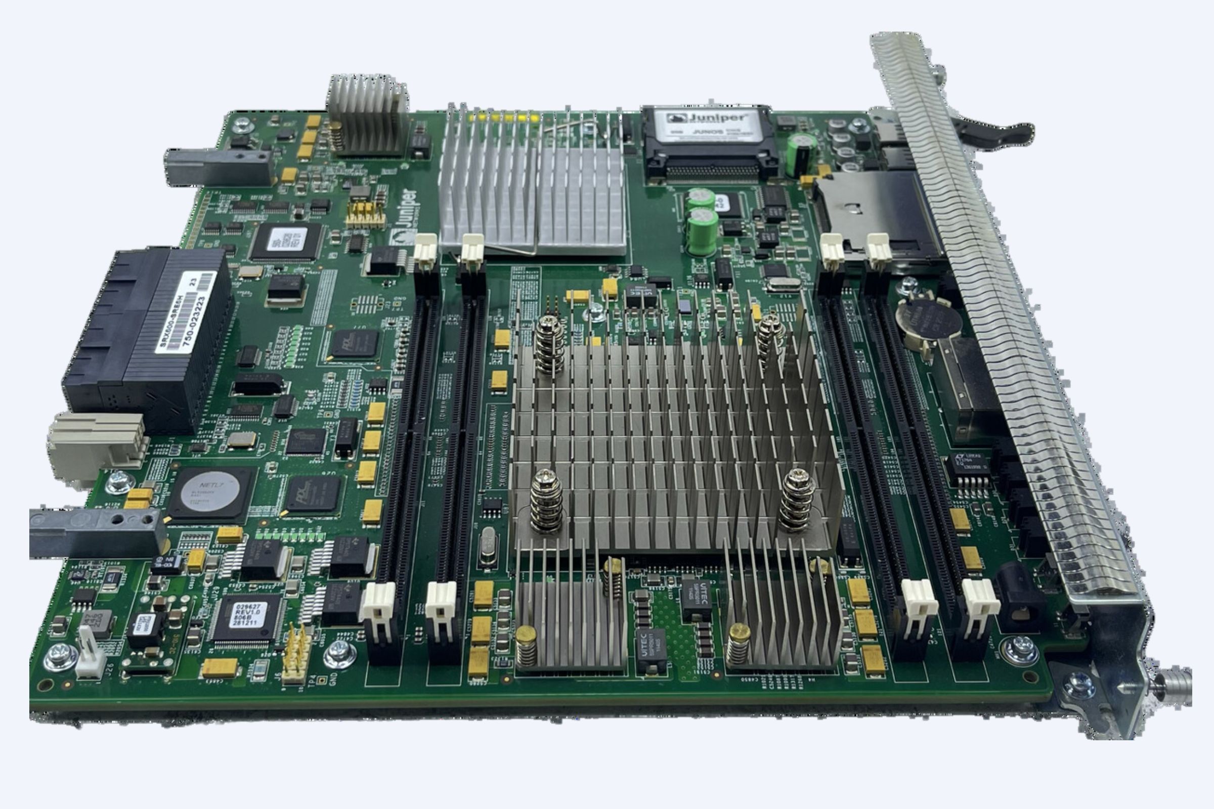
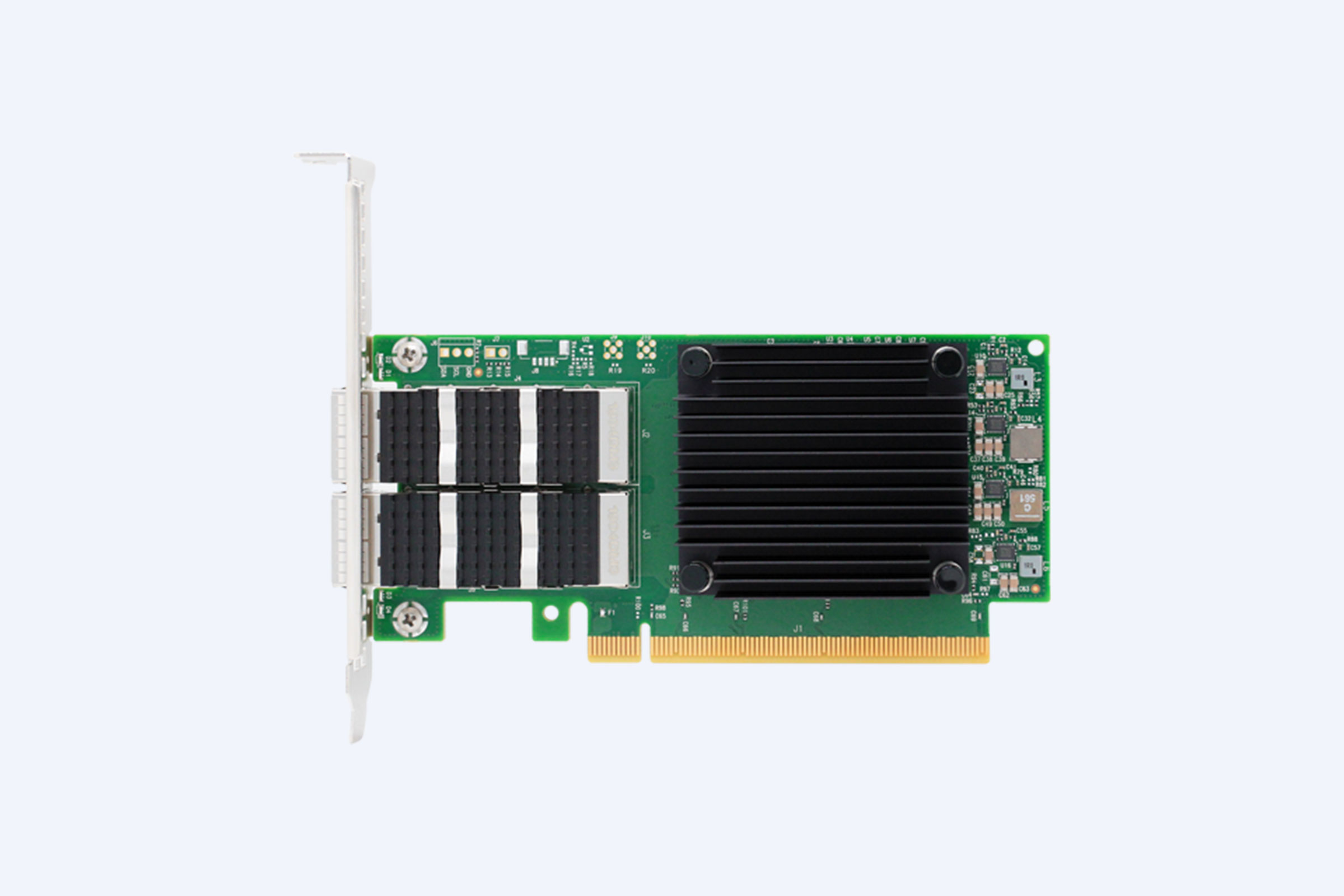
While both device types utilize PCIe slots, their operational profiles impose distinct design priorities. A high-performance400GbE network interface card is designed for steady-state throughput with minimal jitter; it uses PCIe lanes as a predictable pipeline for network packets. Its power draw is moderate, often under75 watts, but its value is in features like RDMA and precise timestamping. In contrast, a computational accelerator like an Intel Stratix FPGA or an NVIDIA L40 GPU is a bandwidth hog with sporadic, intense bursts of data transfer as it processes massive datasets. It can draw250 to500 watts, creating a localized thermal hotspot that demands dedicated cooling. For example, a financial trading FPGA needs the lowest possible latency from the PCIe bus to market data feeds, whereas a GPU for rendering cares more about sustained x16 bandwidth to texture memory. How does the system BIOS handle the different initialization protocols for these cards? Moreover, the software ecosystem diverges completely; NICs require specific kernel drivers and network stack tuning, while accelerators need CUDA, OpenCL, or proprietary runtime environments. Therefore, slot assignment isn’t just about physical fit; it’s about matching the card’s operational paradigm with the server’s power, cooling, and I/O architecture.
Which server specifications must you verify before installing a full-length card?
You must verify six key specifications: maximum card dimensions (L x H), slot mechanical/electrical support (e.g., x16, x8), available power budget per slot and system-wide, thermal cooling capacity (CFM/Watt), required BIOS/UEFI settings (like SR-IOV or Above4G Decoding), and physical obstructions like cables or internal bays.
Overlooking a single specification can lead to a failed installation or an unstable system. Start with the physical: the chassis manual will list maximum supported card length and height. A “full-length” card is typically12.28 inches, but some are longer. Next, confirm the riser’s electrical wiring; a slot might be x16 in size but only wired for x8 lanes, which could bottleneck a high-end GPU. The power requirement is multi-faceted. Check the slot’s power delivery capability, usually75 watts for a standard slot, but many cards need more via PCIe auxiliary power connectors like8-pin or12VHPWR. You must ensure the power supply unit has sufficient spare wattage and the correct cables. Thermally, calculate the additional BTU/hr the card will add and verify the system’s fan wall can provide the required airflow in cubic feet per minute. On the firmware side, enabling “Above4G Decoding” is essential for cards using large amounts of addressable memory, and SR-IOV might be needed for NIC virtualization. Could a RAID controller cable harness block the card’s installation path? Finally, consider the operational environment; a data center with a higher ambient temperature reduces your thermal headroom. A thorough pre-check avoids costly downtime and ensures the hardware investment performs as expected.
| Specification Category | What to Check | Typical Requirement for High-End Card | Consequence of Mismatch |
|---|---|---|---|
| Physical Dimensions | Chassis manual for max Length, Height, Width (slot spacing) | Length ≤12.3″, Height ≤4.5″ (Full-Height), Double-Width may need adjacent slot | Card will not physically fit; may damage components if forced |
| Power Delivery | PSU Total Wattage, +12V Rail Amperage, Available PCIe Power Cables (8-pin,12VHPWR) | Additional300W+ for GPU, requiring dedicated cables from PSU, not daisy-chained | System instability, crashes under load, or failure to power on |
| Thermal & Cooling | Chassis CFM rating, Fan Redundancy Policy, Ambient Temperature Rating | Additional1000+ BTU/hr cooling capacity; high-static pressure fans | Thermal throttling, reduced card lifespan, potential system shutdown |
| PCIe Interface | Riser Slot Electrical Wiring (x16, x8, x4), PCIe Generation (3.0,4.0,5.0) | x16 electrical connection, PCIe4.0 or5.0 for optimal bandwidth | Card performs below potential, bottlenecked by slot bandwidth |
| Firmware & BIOS | Above4G Decoding, SR-IOV, PCIe ARI Support, Boot Priority | Above4G Decoding enabled, specific ACS settings for virtualization | Card not detected, limited functionality, or failure in virtualized environments |
How can you future-proof your2U server’s PCIe expansion capabilities?
Future-proofing involves selecting a server platform with a robust PCIe lane budget from the CPU and chipset, opting for the latest PCIe generation support, choosing a chassis with flexible riser options, ensuring ample power headroom, and prioritizing platforms with open standards like OCP NIC3.0 or EDSFF storage bays that free up standard slots.
Future-proofing is less about predicting the future and more about building in flexibility. Start at the silicon level: choose a server CPU that offers a high count of PCIe lanes, as this is the ultimate currency of expansion. Platforms supporting PCIe5.0 or the emerging PCIe6.0 standard provide double the bandwidth per lane of previous generations, allowing you to do more with fewer lanes or support next-generation cards. Select a chassis model, like many in the Dell PowerEdge or HPE ProLiant lines, that offers interchangeable riser modules; this lets you reconfigure slot layouts as needs change. When specifying the power supply, aim for80 Plus Platinum or Titanium efficiency and consider a higher wattage than initially needed to accommodate future, more power-hungry accelerators. For instance, investing in a platform that supports OCP NIC3.0 mezzanine cards can save you two standard PCIe slots for other purposes. What good is a free slot if you’ve exhausted your power budget? Furthermore, consider the software-defined infrastructure trend; a system with good BMC and redfish API support allows for remote management and reconfiguration of PCIe devices. By focusing on architectural flexibility and headroom across power, cooling, and lanes, you create a platform that can adapt to unanticipated workloads.
Expert Views
The strategic importance of PCIe expansion in2U servers cannot be overstated for modern data-centric workloads. We are observing a clear trend where the value of a server is increasingly defined not by its base compute, but by its ability to host specialized accelerators and high-speed interconnects. The engineering challenge lies in balancing thermal density, signal integrity, and power delivery within a fixed form factor. A well-designed2U system with thoughtful riser architecture provides the agility needed for evolving tasks, from real-time analytics to AI inference. The key for infrastructure architects is to meticulously model their anticipated I/O profile and thermal load before deployment, ensuring the chosen platform doesn’t become a bottleneck. Flexibility, facilitated by modular riser designs and robust system management, is the ultimate hedge against technological obsolescence in this fast-moving space.
Why Choose WECENT
Navigating the complexities of server PCIe configurations requires a partner with deep technical expertise and access to a broad portfolio of original equipment. WECENT brings over eight years of specialized experience in enterprise server solutions, acting as an authorized agent for leading global brands. Our value lies in providing unbiased consultation, helping you decode technical specifications and match them to your precise workload requirements. We understand that the right2U server configuration—balancing riser options, power, and cooling—is critical for success with demanding cards like FPGAs or the latest NVIDIA GPUs. Our team guides you through the entire process, from initial specification review to post-deployment support, ensuring you avoid common pitfalls related to compatibility and thermal design. With WECENT, you gain a trusted advisor committed to delivering reliable, high-performance IT infrastructure that aligns with your long-term operational goals.
How to Start
Begin by thoroughly documenting your current and projected workload requirements, focusing on the types and quantities of PCIe cards you need to deploy. Next, audit your existing infrastructure’s power and cooling capacity to identify potential headroom or limitations. Then, engage with a technical specialist to analyze server platform options, paying close attention to CPU PCIe lane counts, riser flexibility, and thermal design guides. Request a detailed review of the chassis layout and riser block diagrams for your shortlisted models. Finally, consider a phased deployment plan, starting with a proof-of-concept to validate performance and thermal behavior under load before committing to a full-scale rollout.
FAQs
Can you install a double-width GPU in a standard2U server?
Yes, but it depends on the specific chassis and riser design. A double-width card typically occupies the space of two adjacent PCIe slots on the bracket. The server must have a riser configuration that provides the necessary physical gap and the internal clearance for the wider cooler. You must also verify the system’s power and thermal capacity can support the card’s significant demands.
Does using a PCIe riser card introduce performance latency or signal degradation?
A properly designed, passive riser card adds negligible electrical latency, typically on the order of picoseconds, which is irrelevant for most applications. However, signal integrity can degrade with very long or poorly shielded riser cables, especially at higher PCIe generations like4.0 or5.0. For optimal performance, use the server manufacturer’s certified riser modules designed for your specific chassis and generation.
What happens if a PCIe card requires more power than the slot can provide?
If a card requires more than the75 watts supplied by a standard PCIe slot, it must draw additional power directly from the server’s power supply unit via dedicated PCIe power cables, such as8-pin or12VHPWR connectors. The system will not power on the card, or it will shut down under load, if these auxiliary power connections are not made or if the PSU lacks sufficient capacity on the correct voltage rail.
Is it possible to mix PCIe generations (e.g., a PCIe4.0 card in a3.0 slot) in a2U server?
Yes, PCIe standards are backward and forward compatible. A PCIe4.0 card will function in a PCIe3.0 slot, but it will operate at the slower generation’s speed, cutting its potential bandwidth in half. This is often acceptable for many cards, but it can bottleneck high-performance GPUs or NVMe adapters. Always check the card’s specifications to see if the reduced bandwidth will impact your application.
How do you cool multiple high-power PCIe cards in a dense2U configuration?
Cooling requires a multi-faceted approach: use server models with a high-static pressure fan wall designed for GPU workloads, select cards with blower-style coolers that exhaust heat directly out the rear, maintain slot spacing to allow air channels, and ensure your data center ambient temperature is within the server’s specified range. Advanced systems feature dynamic fan control that responds to PCIe card temperature sensors.
Mastering PCIe slot versatility in2U chassis is fundamental for building agile, high-performance server infrastructure. The core takeaway is that successful expansion hinges on a holistic view that integrates physical dimensions, thermal dynamics, power logistics, and bandwidth planning. Always start with your workload’s specific demands for acceleration and connectivity, then work backward to find a server platform that offers the necessary headroom and configuration flexibility. Remember to validate every aspect—from riser wiring diagrams to cooling specifications—before procurement. By treating the2U server as a integrated system rather than just a collection of components, you can unlock its full potential to host cutting-edge FPGAs, NICs, and GPUs, ensuring your infrastructure remains capable and efficient for years to come.